Frequently Asked Questions
General
The most effective way to verify the quality of an EMG signal is to first establish the noise baseline of the system. Delsys EMG systems exhibit 5uV pk-pk noise baseline with the sensor inputs connected to Reference. Once affixed to the skin, the noise baseline is between 5 and 10 uV pk-pk, depending on the impedance characteristics of the skin. This low baseline is observable only when the skin has been carefully cleaned and the muscle is completely relaxed. A soon as the muscle fibers underneath the EMG sensor become activated, individual action potentials can be discerned, appearing at amplitudes as low as 20uV and as high as 2mV. By maintaining a constant contraction level, an estimate of the EMG signal amplitude can be obtained. A signal-to-noise ratio can be computed by calculating the Root-Mean Square (RMS) of the detected signal and dividing it by the RMS noise baseline of the system. The formal signal-to-noise measurement is expressed in decibels, and is calculated as the logarithmic ratio of the RMS signal amplitude to the RMS noise amplitude. The full scale signal-to-noise ratio of our EMG equipment is calculated as follows:
- SNR = 20log(10mV/5uV)
- SNR = 65dB
The antenna design, the communication protocol and the radio hardware have been optimized for trouble-free operation up to 40m in open office environments.
Communication Test:
16 sensors at 20 m for 10 minutes
| Sensor | Dropped Packets | Sensor | Dropped Packets | Sensor | Dropped Packets | Sensor | Dropped Packets |
|---|---|---|---|---|---|---|---|
| 1 | 0 | 5 | 0 | 9 | 1 | 13 | 0 |
| 2 | 0 | 6 | 0 | 10 | 0 | 14 | 0 |
| 3 | 0 | 7 | 0 | 11 | 0 | 15 | 0 |
| 4 | 0 | 8 | 0 | 12 | 0 | 16 | 0 |
Total Packets Sent: 711,112
Total Dropped Packets: 1
Error Rate: < 0.0002 %
Trigno sensors have been meticulously designed to ensure trouble-free operation for distances up to 40m and recording sessions as long as 8 hours. A custom RF protocol operating within the 2.4GHz spectrum has been developed to ensure no data latency between sensors and a high level of transmission robustness. Our approach has minimized the potential for interference from commercially available products that make use of WiFi, Bluetooth, Zigbee and similar RF communication schemes. None-the-less it is advisable to remove any unnecessary 2.4GHz sources from the recording environment when possible. The Trigno System has the ability to track all data packets that are sent from the sensor to the receiving Base Station, so that communication quality at any point in time is known to the system. Multiple sets of operating channels are accessible to the user so that communication quality can be maximized in any given environment.
Equipment Setup
Solution
The Trigno Sensors are required to be paired to a particular slot (1-16) or slots prior to running a data collection. The Trigno Base Station will remember the last paired sensors for each slot, requiring the user to simply turn on the sensors for future collections. They will automatically pair to the previously defined slot(s). If you need to change the sensor slot alignment or incorporate different sensors, then the pairing process will need to be followed, as outlined below.
Turning the Sensor On
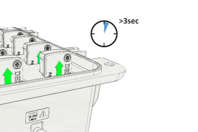
1. Dock the sensor in the charging cradle for 3 or more seconds.
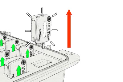
2. Remove the sensor from the cradle. At this point, the sensor will illuminate a white-pinkish LED for 6 seconds.
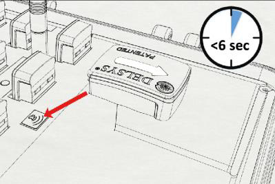
3. While illuminated, tap the sensor to the magnet located on the Base Station. If your Base Station does not have an embedded magnet, any other standalone magnet can be used. If the sensor’s LED turns off, please restart the process from Step 1.
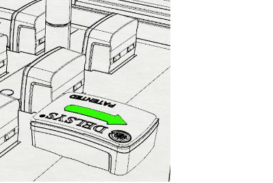
4. The sensor will complete the power up sequence and you’ll notice a green LED appear.
Pairing the Sensors
1. Initiate a pair command from the Trigno Control Utility or the Sensor Status menu found in EMGworks Acquisition (this can be opened by clicking the icon in the top toolbar).

2. After the sensor has been turned on, place the sensor on the magnet.

3. Green blinking LEDs indicate a successful pair operation.

Complete this cycle until all sensors are properly arranged and paired.
Pairing multi-channel sensors – Trigno Quattro, Trigno Galileo and Trigno Duo
By default, these sensors take up more than one of the 16 slots when paired due to the wireless bandwidth required to operate. The Quattro and Galileo Sensors occupy 4 slots, while the Duo occupies 2 slots. Other Trigno Sensors may have modes that increase their slot allotment from 1 to 2 or 4, although these are not by default. For full details on available modes, refer to the Trigno Wireless User’s Guide or specific sensor User’s Guide.
The pairing procedure is the same as above, however, the following rules apply:
- 4-slot sensors can only be paired to slots 1, 2, 3 or 4.
- 2-slot sensors can only be paired to slots 1, 2, 3, 4, 9, 10, 11, or 12.
- When a sensor takes up more than one channel, the associated slots are outlined in blue.

This example shows 4 and 2-slot sensors paired and ready for use.
Solution
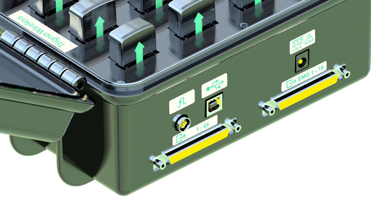
Ensure your base station has analog outputs. A base station with analog outputs will have (2) 68-pin connectors on its side, below the USB, Power and Trigger ports.
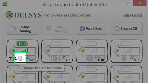
- Once turned on and paired, set each sensor to a mode that samples EMG at 1926 Hz. This will ensure analog outputs will be active when hitting ‘Start Analog’.
- To change sensor settings, click the located within the sensor icon, adjacent to the Pair button.
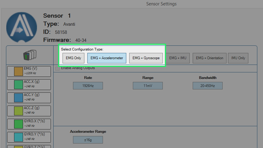
- Choose the appropriate mode. For EMG sensors, this can be done by selecting ‘EMG+Accelerometer’ or ‘EMG+Gyroscope’.
- Users are not required to collect accelerometer or gyroscope data, this simply places the sensors in a mode where EMG analog outputs are supported.
- The base stations 1-16 analog output connector will just contain EMG signals whereas the 1-64 analog output connector will contain EMG+ACC or EMG+GYRO signals.
Users should also be aware of the following details:
- Analog outputs are supported for all Trigno Avanti Sensor types, except:
- Trigno Quattro
- Trigno Galileo
- Trigno Duo
- All analog output signals are capped at a bandwidth of 500 Hz.
- Delsys provides hardware solutions to convert the 68-pin connectors on the Base Station to open wire cables for screw terminal interfaces and BNC breakout boxes.
If you want to learn more about how to interface the Base Station’s analog outputs with your DAQ setup, please reach out to support@delsys.com.
Solution
The Delsys Trigger Module can be used to send out or receive both Start and Stop pulses for synchronization with 3rd-party systems. In this scenario, we will assume the 3rd-party system(s) will be responsible for triggering the Trigno System. Thus, the sync pulse will be generated and sent to the Delsys Trigger Module’s input BNC connectors – the top right (Start) and, if applicable, top left (Stop).
If you wish to have the Delsys Trigger Module send out a sync pulse for starting and/or stopping 3rd-party system(s), simply connect from the output BNC connectors. No other selections are required in the EMGworks software, by default the Trigger Module sends out start and stop sync pulses when the ‘Start’ and ‘Stop’ buttons are pressed in EMGworks Acquisition.
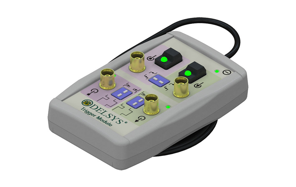
- Plug the
Trigger Module’s connector into the Base Station’s trigger port
 The red dot on the cable’s connector should be facing downwards.
 - Turn the Trigger Module on with the toggle switch. Illuminated light indicates Trigger Module is on.
- Ensure all BNC connectors are secured between the Trigger Module and 3rd-party systems.
- Navigate to the General settings of your Workflow Template tasks in EMGworks Acquisition. Most commonly, users will be working with the Plot and Store template.
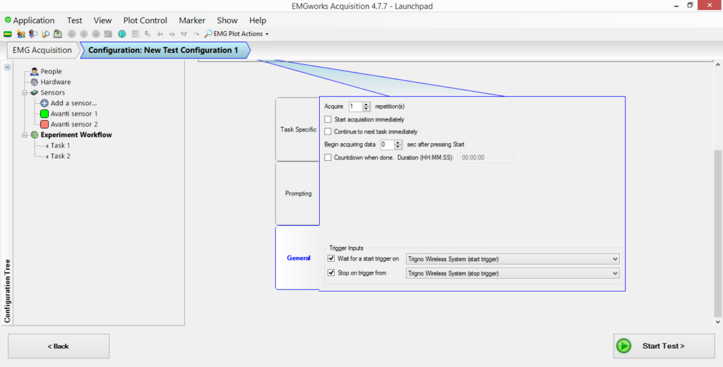
- Depending on your desired trigger setup, choose whether you’ll be using a Start trigger, Stop trigger, or both.
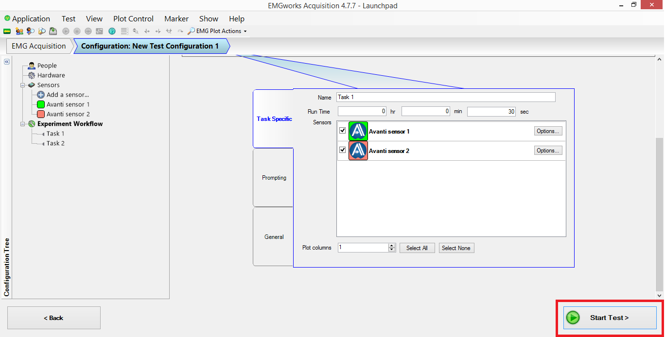
- Click Start Test › Name test run › Okay › Start on recording screen.
- At this point, the system is armed but no data will appear. As soon as the 3rd-party trigger pulse is delivered to the Start input connector, data will stream.
- The recording will end when receiving a Stop trigger (if this option was selected). However, users can still allow the run to end based on the set Run Time or by simply hitting ‘Stop’ on the recording screen.
The Delsys Trigger Module does offer various edge settings and pulse width settings for handling incoming or outgoing synchronization pulses. For complete technical details please refer to the User’s Manual.
Quality EMG signals can only be obtained with proper application of the sensors. EMG signals originate from the movement of very small charged ions in the muscle cell membranes. The skin barrier poses an impediment to the detection of these electric fields from its surface. The impact of the skin in attenuating and possibly distorting these signals can be minimized by ensuring that it is free from extraneous matter which can include hair, oils and dry dermis.
- Remove excessive hair that may occlude a muscle site.
- A brisk wipe using an alcohol swab is effective in removing surface oils and other contaminants. The use of excessive amounts of alcohol will be detrimental as this will cause the skin to dry.
- If dry skin cells are causing difficulties, these can be easily dislodged by dabbing the surface with medical grade tape. Dry skin cells will adhere to the tape and be dislodged when the tape is removed. Ensure that no adhesive residue remains on the skin by wiping the areas with an alcohol swab.
- In cases when skin surface is persistently dry, a very small amount of ionic soap or saline solution can be used to line the EMG sensor contacts. This solution will add electrolytes to the sensor-skin interface, facilitating the necessary ionic exchanges that must occur. Excessive amounts of ionic soap will be detrimental as this could short out the sensor inputs or interfere with the adhesive features of the sensor interfaces. Liquinox (R) brand name soap is an example of an ionic surfactant that can be used for this purpose. This hospital grade detergent should be diluted with a ratio of 50 to 1.
- Proper sensor application requires the use of the Delsys Sensor Interface which is specifically designed to promote strong skin adhesion, to minimize movement artifacts, and to manage the build-up of surface sweat over the coarse of long-duration and/or vigorous activities. Using sensor attachments or approaches other than this one will most likely result in decreased signal quality.
Delsys sensors can be cleaned with a isopropyl alcohol or a mild detergent solution. Gas sterilization methods are also acceptable. Sensors should not be fully submersed in liquids for any period of time. It is recommended to clean Delsys Sensor before and after each use.
EMGworks
The EMGworks Software installer contains the following programs and utilities:
- EMGworks Acquisition
- EMGworks Analysis
- Trigno Control Utility (Software Development Kit Server)
- Delsys File Utility
- Delsys Software Update Tool
User Account Requirements:
EMGworks should be installed while logged in as an Administrator on the Windows PC. The program requires complete permission to access locations like the user AppData folder and Registry Editor.
Without proper admin permission to these locations, the installer may fail to complete. Please confirm the User Account privileges if EMGworks fails to install.
Recommended PC Specifications:
- Windows 7 or higher.
- 2.0 GHz base processor clock speed or higher.
- At least 4 GB system memory.
- At least 128 MB graphics memory.
The Delsys NeuroMap Software contains its own list of specifications, which vary from EMGworks.
Solution
The .hpf data files created when running EMGworks Acquisition are named according to the following guide.
Ex: Run_number_1_Plot_and_Store_Rep_1.0
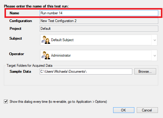
Test Run Name– Name of the overall test, which appears in each file for all upcoming tasks and repetitions. Users generally use a Subject ID or Experiment Name, although it is purely up to the user.
Task Name– Name of each workflow template.
Ex. If using multiple Plot and Stores, each one will have its own name. Suggested names would be the activity performed, such as ‘Walking’ or ‘Running’.
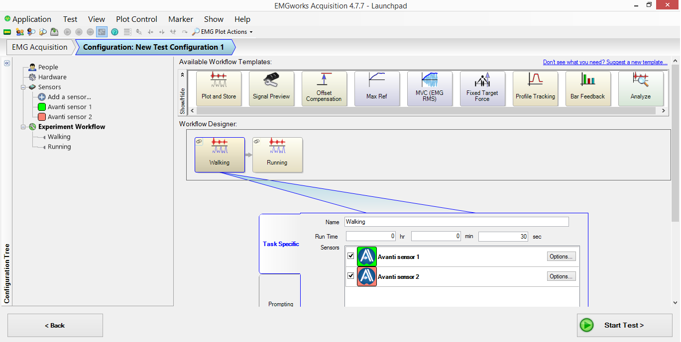
Task Number- The number counter associated with each run performed using a single Workflow Template.
Ex. Walking is Task #1. Running is Task #2.
Overall Rep Number- The number counter associated with each run performed while EMGworks Acquisition has been open.
Ex. You have two Plot and Stores. One named ‘Walking’ and one named ‘Running’. The protocol consists of 3 ‘Walking’ trials followed by 3 ‘Running’ trials. The Subject ID is ‘Subject A’. The 6 files will be named.
- Subject_A_Walking_Rep_1.0
- Subject_A_Walking_Rep_2.1
- Subject_A_Walking_Rep_3.2
- Subject_A_Running_Rep_1.3
- Subject_A_Running_Rep_2.4
- Subject_A_Running_Rep_3.5
EMGworks Analysis
The Workspace, Calculations and Plots are saved in the workspace folder as:
- .ewp: Workspace file. Users can open an entire saved EMGworks Analysis Workspace by simply opening this file.
- .emc: Calculation outputs
- .emp: Plots generated from .emc or .hpf files
Data files are saved as:
- .hpf: Raw data from EMGworks Acquisition
- .shpf: Raw data from Android applications:
- .emtx: File generated with the “Analysis” Workflow Template. This is used by the software to locate the .hpf file. It does not contain data.
Solution
Data is saved in the location specified in the ‘Test Run Name’ window that appears after selecting ‘Start Test’. This dialog box allows users to change the file storage location prior to each data collection.
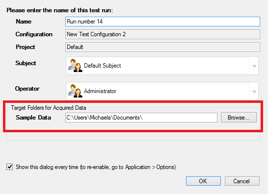
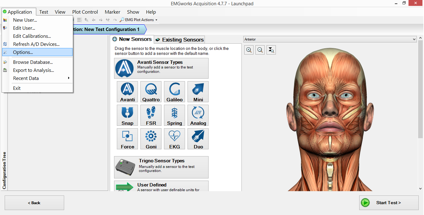
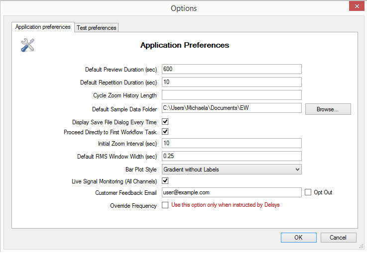
By default, the .hpf files will be saved in the users documents folder, however you can redirect this accordingly by going to:
Application › Options… › Default Sample Data Folder › Choose new file storage location.
Solution
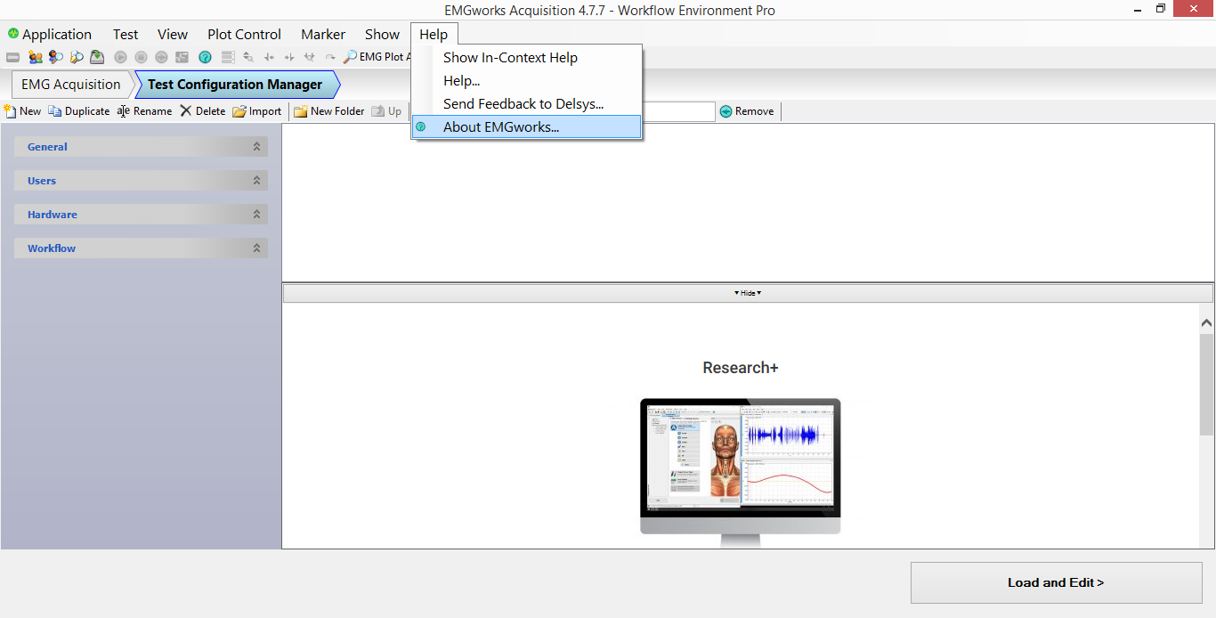
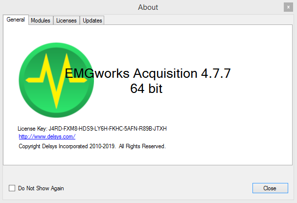
- Open EMGworks Acquisition.
- Select Help › About EMGworks
- Your EMGworks license key will be the 32-digit alphanumeric code that appears below the logo
Troubleshooting
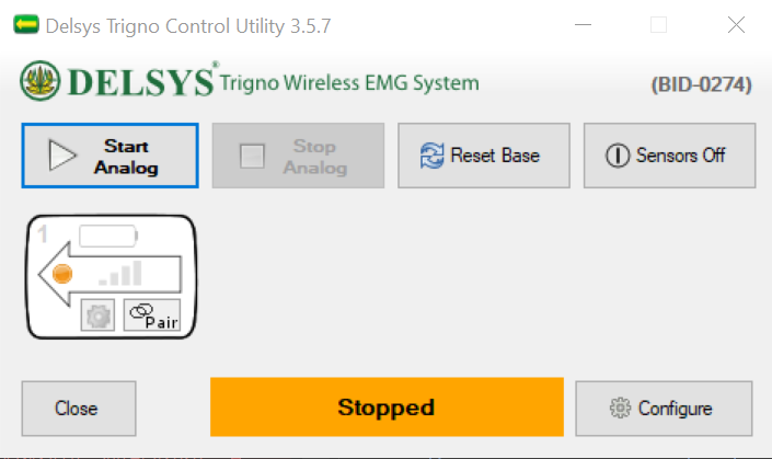
Compromised Trigno Control Utility or Sensor Status interface.
Solution
- Close all Delsys programs.
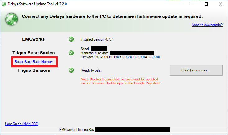
- Open the Delsys Software Update Tool. This gets installed with your other Delsys programs and is located within C:\Program Files (x86)\Delsys, Inc.
- Allow the Update Tool to query your base station information.
- Click Reset Base Flash Memory.
- Wait 5 seconds and close the Update Tool.
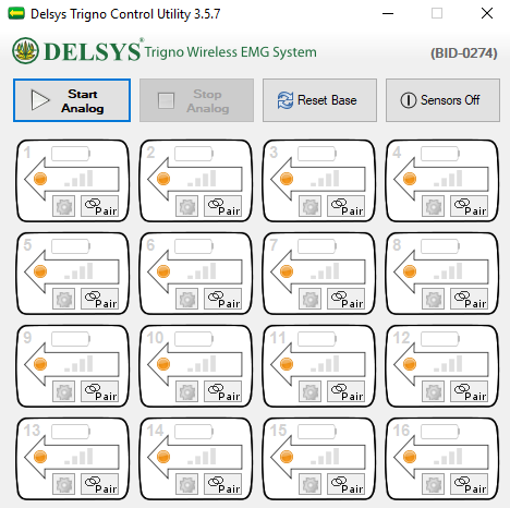
- Open Trigno Control Utility or EMGworks Acquisition and confirm 16 sensor icons appear in the interface.
Proper Trigno Control Utility or Sensor Status interface.
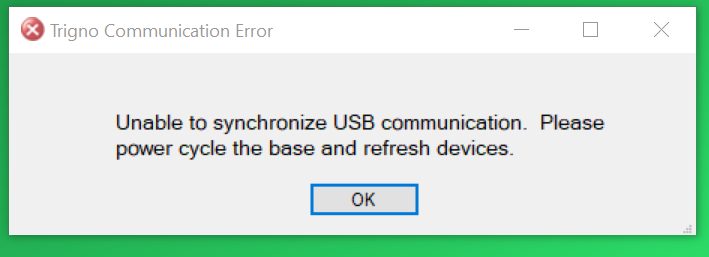
Solution
- Close all Delsys programs.
- Disconnect the Trigno Base Station’s power supply.
- Wait 5 seconds and reconnect the power supply.
- Open the Delsys program of your choosing.
If the problem persists, please follow our firmware guide to ensure you’re running compatible versions of the Trigno software and firmware.
Solution
- Go to the Windows Task Manager and make sure to close any instances of a Delsys program that may be running in the background.
- Navigate to one or both of the following locations, depending on which ones exist on your PC:
- Navigate* to the following location C:\Users\[username]\AppData\Roaming\Delsys, Inc\EMGworks
- Delete all .XML files.
- Navigate* to the following location C:\Users\[username]\AppData\Roaming\SensorBaseControl\SensorBaseControl
- Delete all .XML files.
- Navigate* to the following location C:\Users\[username]\AppData\Roaming\Delsys, Inc\EMGworks
- Re-attempt to open EMGworks Acquisition and/or Trigno Control Utility.
*The AppData folder on your PC may be hidden. To show hidden files and folders, follow the steps below:
- Open File Explorer from the taskbar.
- Select View › Options › Change folder and Search Options.
- Select the View tab and, in Advanced settings, select Show hidden files, folders, and drives. Select Apply › OK
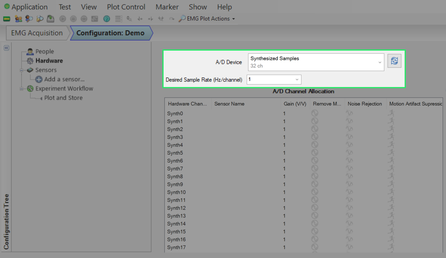
Solution 1
- Select the dropdown menu circled above and select Trigno Wireless System if possible.
If the Trigno Wireless System is not an option, please proceed to Solution 2.
Solution 2
- Close the EMGworks program.
- Disconnect the Trigno Base Station’s power supply.
- Wait 5 seconds and reconnect the power supply.
- Open EMGworks Acquisition and navigate back to Test Configuration’s Hardware tab.
- Select Trigno Wireless System.
- If still unavailable, make a new Test Configuration.
Solution 3
If the problem persists, please follow our firmware guide to ensure you’re running compatible versions of the Trigno software and firmware.
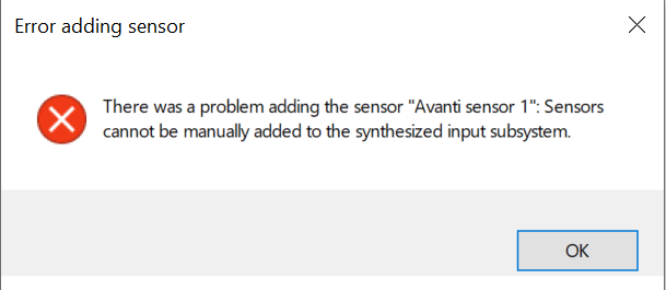
Solution
This error is a result of the Trigno Base Station not being selected or recognized in the Test Configuration. Follow the steps from Why is my Trigno system not appearing as a hardware choice in EMGworks Acquisition? to resolve.

Solution
There are several instances that may prompt this message to appear, but it is mostly attributed to the first point below:
- This message appears commonly at the beginning of setup while sensors are being turned on and paired in preparation for data collection.
- This can be considered normal operating behavior.
- A Trigno Sensor has either been moved out of range from the receiver or turned off (accidentally or purposefully).
- If you’re actively streaming data, ensure you’re still collecting the expected signals.
- If the signals you’re seeing in real-time are not expected, stop the collection and re-pair the sensor. Confirm its status in the Control Utility or Sensor Status window before starting again. Ensure you’re recording within the guaranteed range of the Trigno Base Station.
Essential Firmware and Software Guidelines
Delsys Trigno wireless sensors and base stations rely on “firmware,” which is code that’s programmed onto the hardware and controls many different aspects of the equipment, such as sensor settings, sampling rates, wireless communication, and even how the data is output. As such, ensuring that you’re operating with the appropriate firmware versions is crucial for using the Delsys Trigno system.
You may be required/requested to adjust your firmware in a few scenarios including, but not limited to:
- Using newly purchased equipment with existing equipment;
- Release of a new software version that you’d like to install;
- An error message prevents use of the system/software
Important Notes:
- If your existing setup is fully functional as-is and you are not planning to make any adjustments, you do not need to change your software or firmware versions.
- If you’re integrating your Delsys equipment with 3rd party devices, please check with Delsys regarding integration compatibility before performing any updates.
- Base station can be used with just an SDK installed; HOWEVER, users in this scenario will be asked to install EMGworks by following these steps. EMGworks comes with an SDK by default.
- When changing EMGworks versions, your existing Test Configurations will not carry over.
- While going through these steps, you may encounter notices stating that the version you’re using is out-of-date. “Out of date” and “incompatible” are distinct differences; it is OK to be “out of date” as long as your equipment is compatible. The Version Guide found in these steps should be your main guide for this process, not the “out of date” notifications that appear.
- These instructions will pertain ONLY to the Trigno brand of equipment (excluding TPM). For information on all other Delsys equipment brands (which have all been discontinued), please contact Delsys Support at support@delsys.com.
Note which equipment you’re using
Sensors
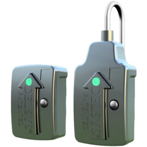
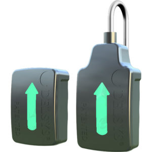
| Sensor Type | Legacy (IM and non-IM) | Avanti |
|---|---|---|
 |
 |
|
| Description | Button, raised arrow, small LED | No button, flat arrow, entire arrow is an LED |
Receiver
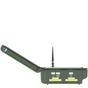
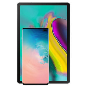
| Receiver Type | Base Station (compatible with Legacy and Avanti sensors) | Tablet/Phone (compatible with Avanti sensors only) |
|---|---|---|
 |
 |
|
| Description | Desktop receiver, holds 16 sensors, connects to PC via USB | Delsys recommends use of the Samsung Galaxy Tab S2, S3, or S5e for tablets; and the Galaxy S9 or S10 for phones. Delsys Trigno Avanti Sensors are only compatible with Android OS. |
Software
| App | EMGworks | SDK | API | Android App |
|---|---|---|---|---|
| Description | Delsys-made PC-based acquisition & analysis software | Running the Delsys Trigno Control Utility enables acquisition into 3rd party software | You are using a self-designed acquisition platform | Delsys-made Android apps for biofeedback, reporting, and data logging |
Third-party system(s)
Note the hardware/software brands and models, software versions, and if/how it’s integrated with Delsys.
Open our Version Guide to know which software and firmware versions are compatible with each other AND the hardware that you are using.
Check and modify current software & base station firmware versions as needed.
This guide will walk you through:
- Installing the Software Update Tool (page 1)
- How to check your current versions (pages 2-3)
- Changing your EMGworks version (page 4)
- Upgrading and downgrading your base station firmware (pages 5-9)
Check and modify firmware of an individual sensor. Repeat for ALL sensors.
For Avanti Sensors, this guide will walk you through:
- Downloading the Firmware Upgrade Tool (page 1)
- How to check your current sensor version (pages 2-4)
- Upgrading your sensor’s firmware (page 5)
- Downgrading your sensor’s firmware (pages 6-7)
For Legacy Sensors, this guide will walk you through:
- Installing the Software Update Tool (page 1)
- How to check your current sensor version (pages 2-4)
- Upgrading your sensor’s firmware (pages 5-7)
- Downgrading your sensor’s firmware (pages 8-10)
